
Assignment 6: Electric bugle

Due at: 5:00pm, Thursday, March 14 Point value: 40 pts Groupwork: You must work in pairs as assigned below.
A. Britton, Clary B. Bucuti C. Inema, John D. Kimenyi, McNew E. Laborde, Yociss
Electronics kit links from previous assignment:
Breadboard inventory
Training for the Digital Laptop Trainer
Breadboarding rules
IC diagrams (alternative reference)
Our goal in thas assignment is to build a fairly sophisticated circuit: an electric bugle.
The traditional bugle is essentially a trumpet without any keys. The lack of keys severely limits the notes that the bugle can play. In fact, traditional bugle music has only four tones — a low G, a C, an E, and a high G. (Some scores also include a low C, but these are relatively rare.) In fact, this restricted set of notes is precisely what makes it useful for our purposes: It allows us to build a fairly simple circuit.
Even though there are only four notes, there are many well-known bugle calls that you'll be able to play. These calls originate in the military, where the bugle is traditionally used to send signals to troops. One of the simplest is Taps, which was traditionally the signal for the troops to go to bed, but which you'll more likely recognize from military funerals. (The dashes below signify long notes.)
low G, low G, C—;
low G, C, E—;
low G, C, E—, low G, C, E—, low G, C, E—;
C, E, high G—;
E—, C—, low G—;
low G, low G, C—.

You'll also likely recognize Reveille (the signal for the
troops to wake up), First Call (familiar from horse races),
and Mess Call (a staple for pep bands at sporting events).
Wikipedia's bugle
call
article has the musical scores for these and many other
bugle calls. Nearly all are tunes that you'll be able to play with
your electric bugle.
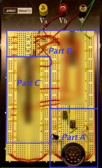
We'll construct the circuit in three parts; the picture above is of my solution, with outlines showing where I chose to place my solution for each part. I don't need to see your circuit until you've completed the entire circuit.
Part A: Playing a tone
First, we'll construct the circuit for playing sounds. This isn't a circuit that we'll attempt to understand: We just want to build it and make sure it works.
You should construct your entire circuit on the black prototyping board, rather than the digital trainer. You'll still make use of the digital trainer's components, but not its breadboard. I recommend placing the circuit for Part 1 at the bottom right corner of the prototyping board. It should be relatively compact, to leave plenty of room for later parts.
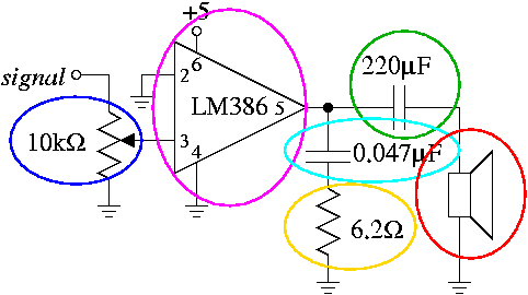
Below is a circuit diagram with an overhead photograph of the corresponding circuit constructed. Corresponding sites in each are circled with corresponding colors.
|

|
Notes:
The right-pointing triangle in the circuit diagram references the LM386 IC, which despite its appearance is not a digital component. The numbers within the triangle reference the different pins on the IC, counting counterclockwise starting from the notch as with the other ICs we have seen. The unmentioned pins 1, 7, and 8 should be left disconnected.
Note the color bands on the resistor. The sequence blue-red-gold-gold indicates that it has a resistance of 6.2Ω. Your kit also includes four 2.2kΩ resistors, which you need for Part B; these are identified by a band sequence of brown-red-red-gold.
The signal input, which feeds into the
potentiometer (circled in blue), should come from your trainer's
fast clock
(J18), which runs around 2 kilohertz. If your
circuit works, you'll hear a constant tone at an irritatingly
high pitch. That's because 2 kilohertz is a very high tone; in
Part C, we'll divide
the tone into smaller
frequencies, yielding tones in a more pleasant range.
Part B: Playing no tone
Now we'll construct the circuit so that it contains four buttons.
When any of the four buttons is down, the speaker will play a tone,
but for now, all buttons result in the same one. This is simply a
matter of taking the XOR of all the button results, to see whether an
odd number is pressed. (This way, if the user is pressing two buttons,
as happens when somebody plays a tune quickly, the two notes will
cancel out
.) Then, you would AND this with the clock signal. The
result of the AND gate is fed into the amplifier circuit driving the
speaker. Thus, if zero or two buttons are depressed, the AND gate
will be a constant zero, and so the speaker would emit no noise.
Below is a circuit diagram of how to connect the four buttons, with an accompanying photograph. I suggest placing the buttons in the upper left corner of the prototyping board and placing the silencing circuit in the upper right corner — but leave about 7 empty rows at the top of the right column. (You'll find some empty rows here useful for Part C.)

|

|
Part C: Playing different tones
The last part is the most challenging: We need to generate tones of
different frequencies, depending on which of the four switches is being
pressed. To do this, we'll divide
the fast clock by 6 (high G), 7
(E), 9 (C), or 12 (low G), depending on which button is down. For
example, if the high-G button is pressed, then our circuit will produce
a wave that goes up after every 6 cycles of the fast clock, then goes
down after every 6 cycles.
You should wire your buttons so that the leftmost (or uppermost) button corresponds to division by 12, the next button is 9, the next is 7, the next is 6. This way, the notes get higher as you progress to the right, just as a piano keyboard.
To divide
the clock, we'll use a counter, namely the
74LS161.
You might at first think that would divide the clock by using
the clock to count from 0; upon reaching 5
(or 6, or 8, or 11), we'd then toggle the signal that is
actually sent to the speaker. If we count up from 0, though, then we'd
need to build a circuit to test whether we've reached one of four
numbers, depending on which button is down. A simpler technique
turns out to be to start at the appropriate number and then count up
to 15. Conveniently, the 74LS161 has a carry out
signal that signifies when it has reached 15, at which point you'll want
the counter to load in the starting value again.
You'll want to use a D flip-flop, whose value will toggle between 0 and 1 each time the counter starts over again; this will be the signal that will be sent to the speaker (after going through the circuit of Part B). You can use the signal from the counter as a clock for the D flip-flop.
Before connecting your circuit to the speaker, you should first test it: Otherwise, even if it sounds like your circuit works, you wouldn't be completely sure. To test it, connect the counter's outputs to the trainer's hexadecimal display, connect the D flip-flop's output to one of the trainer's LEDs, and drive the counter using the slow clock (J17). You should be able to test each of the buttons, to see that the LED inverts every 6/7/9/12 clock cycles.
(By the way, the E note is actually slightly off-key: With the high-G being 6 cycles long, the E should really be 7.2 cycles. We can only count integers, though, so we approximate by 7. All notes would be perfect if we used division by 10, 12, 15, and 20. But counting 20 clock cycles requires a five-bit counter, which significantly complicates the assignment. The choice of 6/7/9/12 is the best that can be managed using a four-bit counter, and it's close enough that you probably won't notice unless you have a well-trained ear and you're listening for it.)