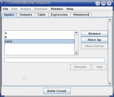
On opening the Combinational Analysis window, you will see that it consists of five tabs.

The Inputs tab allows you to view and edit the list of inputs. To add new inputs, type it in the field at the pane's bottom, and click Add. If you want to rename an existing input, select it in the list in the pane's upper left region; then type the name and click Rename.
To remove an input, select it from the list and click Remove. You can also reorder the inputs (which affects the order of columns in the truth table and in the generated circuit) using the Move Up or Move Down buttons on an input.
All actions affect the truth table immediately.
The Outputs tab works in exactly the same way as the Inputs tab, except of course it works with the list of outputs instead.
The only item under the Table tab is the current truth table, diagrammed in the conventional order, with inputs constituting the columns on the left and outputs constituting the columns on the right.
You can edit the current values appearing in the output columns by clicking on the value of interest. The values will cycle through 0, 1, and x (representing a "don't care"). As we'll see on the next page, any don't-care values allow the computation of minimized expressions some flexibility.
If the truth table is based on an existing circuit, you may see some pink squares in the output columns with "!!" in them. These correspond to errors that occurred while calculating the value for that row - either the circuit seemed to be oscillating, or the output value was an error value (which would be pictured as a red wire in the Logisim circuit). Hovering your mouse over the entry should bring up a tool tip describing which type of error it was. Once you click on the error entry, you will be in the 0-1-x cycle; there is no way to go back.
Next: Creating expressions.