Every tool for adding components to a circuit also has a set of attributes, which are imparted to the components created by the tool, although the components' attributes may be changed later without affecting the tool's attributes. When you select a tool, Logisim will change the attribute table to display that tool's attributes.
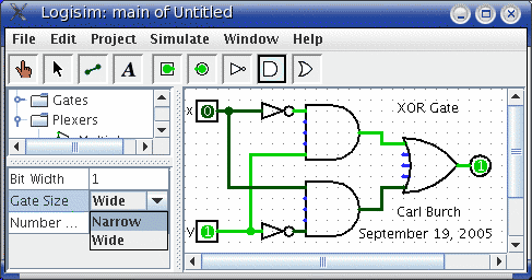
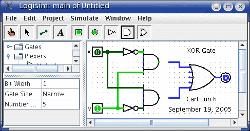
For example, suppose we want to create smaller AND gates. We've already seen that an AND gate's Gate Size attribute is not editable. But the Gate Size attribute is editable for the AND gate tool: To view and edit this attribute, click the tool's icon in the toolbar (or the explorer pane), and change its Gate Size attribute.
The tools in the toolbar each have a separate attribute set from the corresponding tools in the explorer pane. Thus, even though we changed the toolbar's AND tool to create narrow AND gates, the AND tool in the Gates library will still create wide AND gates unless you change its attributes too.
In fact, the input pin and output pin tools in the default toolbar are both instances of the Base library's Pin tool, but the three attribute sets are different. The icon for the Pin tool is drawn as a circle or a square depending on the value of its ``Output?'' attribute.
Logisim provides a handy shortcut for changing the Facing attribute that controls the direction in which many components face: Typing an arrow key while that tool is selected automatically changes the direction of the component.
Next: User's Guide.