Every input and output on every component in the circuit has a bit width associated with it. Many of Logisim's built-in components include attributes allowing you to customize the bit widths of their inputs and outputs.
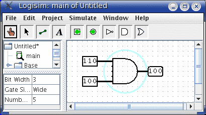
The below screen shot illustrates a simple circuit for finding the bitwise AND of two three-bit inputs; each pin has its Bit Width attribute customized for dealing with three-bit data, as with the pictured AND gate attributes.
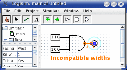
For components, all inputs and outputs must have their bit widths defined. In contrast, a wire's bit width is undefined: Instead, the wire's width adapts to the components to which it is attached. If a wire connects two components demanding different bit widths, Logisim will complain of ``Incompatible widths'' and indicate the offending locations in orange. In the below, the output pin's Bit Width attribute has been changed to 1, and so Logisim complains that the wire cannot connect a three-bit value to a one-bit value.
For single-bit wires, you can see at a glance what value it
is carrying because Logisim colors the wire light
or dark green depending the value.
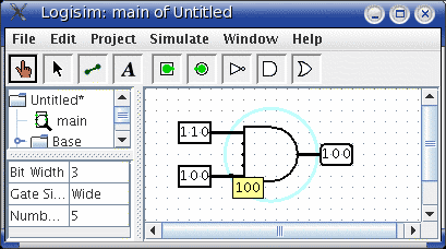
It does not display values for multi-bit wires: They are simply
black. You can, though, probe a wire by clicking it using the
poke tool (![]() ).
).
Next: Splitters.