|
| XOR/XNOR/Odd Parity/Even Parity Gate |
| Library: | Base |
| Introduced: | 2.0 Beta 1 for XOR/Odd/Even; 2.0 Beta 6 for XNOR |
| Appearance: | 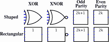 |
The XOR, XNOR, Even Parity, and Odd Parity gates each compute the respective function of the inputs, and emit the result on the output. The two-input truth table for the gates is the following.
| x | y | XOR | XNOR | Odd | Even |
|---|---|---|---|---|---|
| 0 | 0 | 0 | 1 | 0 | 1 |
| 0 | 1 | 1 | 0 | 1 | 0 |
| 1 | 0 | 1 | 0 | 1 | 0 |
| 1 | 1 | 0 | 1 | 0 | 1 |
Any inputs that are unspecified (i.e., floating) are ignored. If all inputs are floating, then the output is floating, too. If any of the inputs are the error value (e.g., if conflicting values are coming into the same wire), then the output will be the error value, too.
The multi-bit versions of each gate will perform its one-bit transformation bitwise on its inputs.
Note: Many authorities contend that the shaped XOR gate's behavior should correspond to the odd parity gate, but there is not agreement on this point. Logisim's behavior for XOR gates is based on the IEEE 91 standard. It is also consistent with the intuitive meaning underlying the term exclusive or: A waiter asking whether you want a side dish of mashed potatoes, carrots, peas, or cole slaw will only accept one choice, not three, whatever some authorities may tell you. (I must admit, though, that I have not subjected this statement to a rigorous test.)
Note that if you are using shaped gates, the west side of XOR and XNOR gates will be curved. Nonetheless, the input pins are in a line. Logisim will draw short stubs illustrating this; and if you overshoot a stub, it will silently assume that you did not mean to overshoot it. In "printer view", these stubs will not be drawn unless they are connected to wires.
None.
None.