|
| AND/OR/NAND/NOR Gate |
| Library: | Base |
| Introduced: | 2.0 Beta 1 |
| Appearance: | 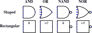 |
The AND, OR, NAND, and NOT gates each compute the respective function of the inputs, and emit the result on the output. The two-input truth table for the gates is the following. (The letter X represents the error value, and the letter Z represents the floating value.)
|
| |||||||||||||||||||||||||||||||||||||||||
|
| |||||||||||||||||||||||||||||||||||||||||
Normally, any inputs that are left unconnected are ignored. If all inputs are unconnected, the output is the error value X. If, however, the "Gate Output When Undefined" option is "Error for undefined inputs," then the output will be the error value if one or more of the inputs are floating.
The multi-bit versions of each gate will perform its one-bit transformation bitwise on its inputs.
The inputs into the component. There will be as many of these as specified in the Number of Inputs attribute.
Note that if you are using shaped gates, the west side of OR and NOR gates will be curved. Nonetheless, the input pins are in a line. Logisim will draw short stubs illustrating this; and if you overshoot a stub, it will silently assume that you did not mean to overshoot it. In "printer view", these stubs will not be drawn unless they are connected to wires.
The gate's output, whose value is computed based on the current inputs as described above.
None.
None.