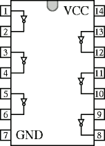
74LS08 quad 2-in AND gate
74LS32 quad 2-in OR gate
74LS86 quad 2-in XOR gate

Pin 2: input to first gate
Pin 3: output of first gate
Pin 4: input to second gate
Pin 5: input to second gate
Pin 6: output of second gate
Pin 7: ground
Pin 13: input to third gate
Pin 12: input to third gate
Pin 11: output of third gate
Pin 10: input to fourth gate
Pin 9: input to fourth gate
Pin 8: output of fourth gate

Pin 2: input to first gate
Pin 3: input to first gate
Pin 4: output of second gate
Pin 5: input to second gate
Pin 6: input to second gate
Pin 7: ground
Pin 13: output of third gate
Pin 12: input to third gate
Pin 11: input to third gate
Pin 10: output of fourth gate
Pin 9: input to fourth gate
Pin 8: input to fourth gate
Pin 2: output of first gate
Pin 3: input to second gate
Pin 4: output of second gate
Pin 5: input to third gate
Pin 6: output of third gate
Pin 7: ground
Pin 13: input to fourth gate
Pin 12: output of fourth gate
Pin 11: input to fifth gate
Pin 10: output of fifth gate
Pin 9: input to sixth gate
Pin 8: output of sixth gate

Pin 2: value to be loaded into first bit
Pin 3: on positive edge, load pin 2 to first bit
Pin 4: when low, set first bit to 1
Pin 5: current value of first bit
Pin 6: inverse value of first bit
Pin 7: ground
Pin 13: when low, clear second bit to 0
Pin 12: value to be loaded into second bit
Pin 11: on positive edge, load pin 12 to second bit
Pin 10: when low, set second bit to 1
Pin 9: current value of second bit
Pin 8: inverse value of second bit

Pin 2: when low, set first bit to 1
Pin 3: when low, clear first bit to 0
Pin 4: J input for first flip-flop
Pin 5: +5 volts
Pin 6: on positive edge, update second bit
Pin 7: when low, set second bit to 1
Pin 8: when low, clear second bit to 0
Pin 15: current value of first bit
Pin 14: inverse value of first bit
Pin 13: ground
Pin 12: K input for second flip-flop
Pin 11: current value of second bit
Pin 10: inverse value of second bit
Pin 9: J input for second flip-flop
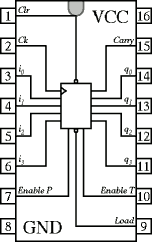
Pin 2: on positive edge, update counter
Pin 3: 1's bit of value to be loaded
Pin 4: 2's bit of value to be loaded
Pin 5: 4's bit of value to be loaded
Pin 6: 8's bit of value to be loaded
Pin 7: when high, enable counter update
Pin 8: ground
Pin 15: is high when current value is 15
Pin 14: 1's bit of current value
Pin 13: 2's bit of current value
Pin 12: 4's bit of current value
Pin 11: 8's bit of current value
Pin 10: when high, enable counter update
Pin 9: when low, load pins 3 to 6 on clock edge