
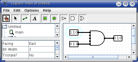
Every input and output on every component in the circuit has a bit width associated with it. Many of Logisim's built-in components allow you to customize their inputs and outputs bit widths through attributes. Below, I have inserted two input pins, an AND gate, and an output pin, all customized to deal with three-bit data.
Wires, however, do not need their bit width specified. Logisim will automatically infer a wire's bit width based on the requirements of the components to which the wire is attached. To connect the input and output pins to the AND gate, we have only to select the wiring tool and draw in three wires.
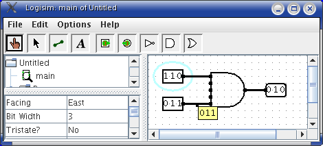
Whereas Logisim shows a single-bit wire's value by coloring it either
light or dark green, it draws multi-bit wires black. To view the
value a wire is currently carrying, probe it with the poke tool ![]() .
.
Next: Splitters.