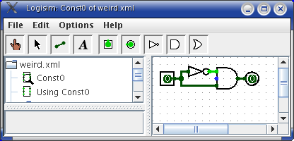
As an example of the level of sophistication of Logisim's algorithm, consider the following circuit, which I've named Const0.

More sophisticated components built into Logisim have larger gate delays, although the values for these gate delays is somewhat arbitrary and may not reflect reality.
From a technical point of view, it is relatively easy to deal with this level of sophistication in a single circuit. Dealing with gate delays across subcircuits, though, is significantly more complex, and very few educational packages handle it correctly (including Logisim prior to version 2.0).
Note that I'm stopping short of saying that Logisim always handles it correctly. But at least it tries.
Next: Oscillation errors.