Next: Step 3: Adding text
After you have all the components blocked out on the canvas, you're
ready to start adding wires. Select the wiring tool (![]() , the third tool in the toolbar's
first group). Then start dragging from
one position to another in the canvas area, and wires will start
appearing between the two points.
, the third tool in the toolbar's
first group). Then start dragging from
one position to another in the canvas area, and wires will start
appearing between the two points.
Wires in Logisim must be horizontal or vertical. To connect the upper input to the NOT gate and the AND gate, then, I had to add three different wires.
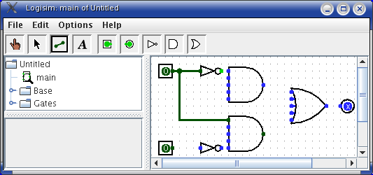
As you draw wires, you may see some blue or gray wires. Blue in Logisim indicates that the value at that point is ``unknown'', and gray indicates that the wire is not connected to anything. This is not a big deal temporarily. But by the time you finish your circuit, none of your wires should be blue or gray. (The unconnecting legs of the OR gate will still be blue: That's fine.)
If you do have a blue or a gray wire, then one of the wires isn't connected as you thought. It's important that you connect wires to the right places. Logisim draws little dots on the components to indicate where wires ought to connect. As you proceed, you'll see the dots turn from blue to light or dark green.
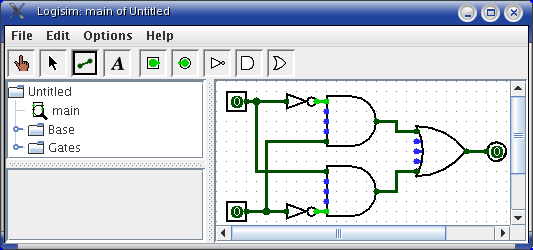
Once you have all the wires connected, all of the wires you inserted will themselves be light or dark green.
Next: Step 3: Adding text