SimHYMN Instruction Set

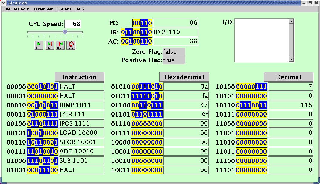
The SimHYMN simulator has 8 instructions, all shown in the first column
of memory above. The 8 bits for each instruction are divided into two
parts. The first three bits (called the op code) determine the
instruction while the last 5 bits are data to be used by that
instruction. In fact, the data part is always a memory location (or,
more properly, a memory address).
In this section, we will introduce and describe each of the 8
instructions. Note that in these descriptions xxxxx simply indicates
the
last 5 bits in the word. They may all be different.
000xxxxx - HALT -
The Op Code 000 represents the HALT
instruction which simply causes the simulator to stop. The 5 address
bits have no effect whatsoever. Thus, we show three examples of HALT instructions. At address
00000 we have 00010101, at 00001 we have 00000000, and at 01001 we have
00011100. All of these HALT
the machine.
001xxxxx - JUMP xxxxx
- The Op Code 001 represents the JUMP
instruction. The effect of the JUMP
instruction is to copy the data bits into the PC. Since the PC holds the address of the
next instruction to execute, the effect of the JUMP is to make that next
instruction be the one at the address xxxxx. For example, memory
location 00010 contains 00101011 so after this JUMP 01011 executes, the PC will contain the last 5
bits
- 01011 - and,
therefore, the next instruction to execute will be the one at 01011. (The instruction at 01011 is, in fact, a SUB instruction - see below.)
010xxxxx - JZER xxxxx
- The Op Code 010 represents the JZER
(Jump on ZERo) instruction. This is the
first of two conditional jump instructions. This instruction has the
effect that if the Zero Flag
is true, the last 5 bits are copied into the PC so that the next
instruction
to be executed will be the instruction whose address is those 5 bits.
If
the Zero Flag is
false, the PC is
simply incremented by 1 so that the next instruction will be the one
after the JZER. For
example, at address 00011 we have 01101111 (JPOS 01111). If our Zero Flag had been true, the PC would have been set to 01111 - the last 5 bits - and
the next instruction would have been the one at 01111 (a HALT instruction). In fact,
since our Zero Flag
is false, the PC
would simply go the next address - 00100.
011xxxxx - JPOS xxxxx
- The Op Code 011 represets the JPOS
(Jump on POSitive) instruction. This is
the second conditional jump instruction. It works exactly like the JZER
instruction except that the last 5 bits are copied into the PC when the Positive Flag is true. Our
example at 00100 would copy 10001 into the PC since our Positive Flag is true.
100xxxxx - LOAD xxxxx
- The Op Code 100 represents the LOAD
instruction. This instruction will copy the value at memory address xxxxx into the AC (the accumulator). At
address 00101 we have 10010000 - LOAD
10000 - so the effect of this instruction would be to take
the value at 10000 - 00000111 (7 decimal) - and copy it into the AC. Thus, the AC would now have value
00000111. There are two special cases. LOAD 11110 does not load a
value
from memory location 11110- note the simulator does not even
show a location 11110. LOAD 11110
does input from the
keyboard. You will be prompted with a question mark in the I/O Window in the upper right
of the simulator and you should type in a decimal number between -128
and +127. This value will be translated into 8-bit 2's complement
decimal and put in the AC after you hit return. This is an example of
what is called memory-mapped input. (You should never do LOAD 11111 since as described in
the STOR description below,
this address, also not shown in the window, is for memory-mapped
output. The Assembler has a
pseudo-op READ which the Assembler translates into LOAD 11110.)
101xxxxx - STOR xxxxx
- The Op Code 101 represents the STOR
instruction. This instruction will copy the value in the AC into the memory location xxxxx. In our example at 00110
we have 10110001 - STOR 10001
- so memory location 10001 would be set to the value in the AC - 00100110. STOR also has the two special
cases STOR 11110
and STOR 11111. You should never do STOR 11110
since that is supposed to be the memory-mapped input address. Also, STOR 11111 cause the decimal
value of the value in the AC
to appear in the IO Window.
This is an example of memory-mapped output. (The Assembler has a pseudo-op WRITE which the Assembler translates into STOR 11111.)
110xxxxx - ADD xxxxx
- The Op Code 110 represents the ADD
instruction. This instruction takes the value from address xxxxx and adds it to the value
in the AC and
stores
the result in the AC.
Thus, for our example at 00111 we have 11010010 - ADD 10010 - and since the
value
at 10010 is 0 when we add the value in AC to it it will be unchanged
and
the result put into the AC.
111xxxxx - SUB xxxxx -
The Op Code 111 represents the SUB
instruction. This instruction takes the value from address xxxxx and subtracts it from
the
value in the AC and
stores the result in the AC.
For our example at 01000 we have 11101101 - SUB 01101 - and since the
value
at 01101 is 01101111 and the AC
contains 00100110, subtracting 01101111 from 00100110 gives the
negative
2's complement result 10110111 which is then stored in the AC.
