- Logisim home page
- Guide to Being a Logisim User
- Library Reference
Tool attributes
Every tool for adding components to a circuit also has a set of attributes, which are imparted to the components created by the tool, although the components' attributes may be changed later without affecting the tool's attributes. When you select a tool, Logisim will change the attribute table to display that tool's attributes.
For example, suppose we want to create smaller AND gates. Right now, each time we select the AND tool, it creates a large AND gate. But if we edit the Gate Size attribute just after selecting the tool (before placing its AND gate into the circuit), we'll be changing the attributes for the tool, so that future AND gates added using the tool would be narrow instead.
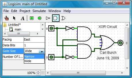
Now, we can delete the two existing AND gates and add two new AND gates in their place. This time, they will be narrow. (If you chose to reduce the number of inputs to 3, the AND gate would not have vertical extension on the left side. But you'd also have to rewire the circuit so that the wires hit the AND gate's left side.)

With some tools, the tool's icon reflects some of the attributes' values. One example of this is the Pin tool, whose icon faces the same way as its Facing attribute says.
The tools in the toolbar each have a separate attribute set from the corresponding tools in the explorer pane. Thus, even though we changed the toolbar's AND tool to create narrow AND gates, the AND tool in the Gates library will still create wide AND gates unless you change its attributes too.
In fact, the input pin and output pin tools in the default toolbar are both instances of the Base library's Pin tool, but the attribute sets are different. The icon for the Pin tool is drawn as a circle or a square depending on the value of its "Output?" attribute.
Logisim provides a handy shortcut for changing the Facing attribute that controls the direction in which many components face: Typing an arrow key while that tool is selected automatically changes the direction of the component.
Next: User's Guide.