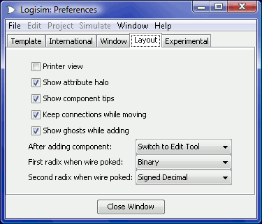
Die Registerkarte "Layouteditor"

This tab includes preferences affecting the behavior of the circuit layout editor.
Printer view: Specifies whether to display the circuit on the screen in the same way it is displayed through the printer. Normally this is off, and Logisim displays the on-screen circuit with indications of the current circuit state, and it displays some hints about component interface (most notably, it draws legs on OR gates to indicate where they would connect). The printer view, though, omits indications of state, and it omits such interface hints.
Show attribute halo: Specifies whether to draw the pale teal oval around the component or tool whose attributes are currently displayed in the attribute table.
Show component tips: Specifies whether to display the "tool tips" that will temporarily appear when the mouse hovers over components supporting them. For example, if you hover over a subcircuit component's pin, it will display the label of the corresponding pin within the subcircuit. Hovering over one of the ends of a splitter will tell you the bits to which that end corresponds. In addition, all components in the Plexers, Arithmetic, and Memory libraries will provide information about their inputs and outputs via tips.
Keep connections while moving: Indicates whether Logisim should add new wires when components are moved to preserve their connections. By default this is on — though it can be turned off temporarily by pressing the shift key while moving the components. If this box is unchecked, then the default will be not to add wires during a move — though you can turn it on temporarily by pressing the shift key during the move.
Show Ghosts while adding: When checked, and when a tool for adding a new component is selected, a light-gray outline of a component to be added is drawn as the mouse moves across the canvas. For example, if you select the AND gate tool and move the mouse into the window (without pressing the mouse's button), a gray outline of an AND gate will display where the AND gate will appear when the mouse is clicked.
After adding component: By default, after adding each individual component, Logisim switches back to the Edit Tool to allow you to move components around and to add wires. The drop-down box allows you to change this behavior so that Logisim stays at the same tool for adding more of the same component, until you yourself opt to choose the Edit Tool. (This was Logisim's default behavior prior to Logisim 2.3.0. While more intuitive, this behavior requires more mouse movement to switch between tools.)
First radix when wire poked: Configures how values are displayed when a wire is clicked using the Poke Tool. Clicking a wire displays temporarily the value, staying until the user clicks elsewhere in the circuit.
Second radix when wire poked: Configures the second part of how wire values are displayed.
Next: The Experimental tab.
