|
| AND/OR/NAND/NOR Gate |
| Library: | Gates | ||||||||||||
| Introduced: | 2.0 Beta 1 | ||||||||||||
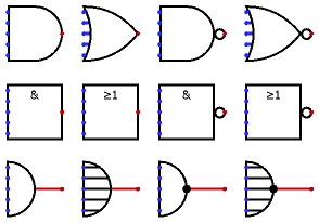
| Appearance: |
|
||||||||||||
Behavior
The AND, OR, NAND, and NOT gates each compute the respective function of the inputs, and emit the result on the output.
By default, any inputs that are left unconnected are ignored
— that's if the input truly has nothing attached to it,
not even a wire.
In this way, you can insert a 5-input gate but only attach two inputs,
and it will work as a 2-input gate;
this relieves you from having to worry about configuring
the number of inputs every time you create a gate.
(If all inputs are unconnected, the output is the error value X.)
Some users, though, prefer that Logisim insist that all inputs be connected,
since this is what corresponds to real-world gates.
You can enable this behavior by going to the Project > Options… menu item,
selecting the Simulation tab, and
selecting Error for undefined inputs
for
Gate Output When Undefined.
The two-input truth table for the gates is the following. (The letter X represents the error value, and the letter Z represents the floating value.)
|
| |||||||||||||||||||||||||||||||||||||||||
|
| |||||||||||||||||||||||||||||||||||||||||
In short, these components work as expected as long as all inputs are either 0 or 1. If an input is neither 0 nor 1 (it is floating or it is the error value) then the component treats it as both 0 and 1: If the output would be the same both ways (as when an AND gate has one input that is definitely 0 and a questionable second input), that will be the output value; but if the output changes depending on whether it is 0 or 1, the output is the error value.
The multi-bit versions of each gate will perform its one-bit transformation bitwise on its inputs.
Pins (assuming component faces east)
- West edge (inputs, bit width according to Data Bits attribute)
The inputs into the component. There will be as many of these as specified in the Number of Inputs attribute.
Note that if you are using shaped gates, the west side of OR and NOR gates will be curved. Nonetheless, the input pins are in a line. Logisim will draw short stubs illustrating this; and if you overshoot a stub, it will silently assume that you did not mean to overshoot it. In "printer view", these stubs will not be drawn unless they are connected to wires.
- East edge (output, bit width according to Data Bits attribute)
The gate's output, whose value is computed based on the current inputs as described above.
Attributes
When the component is selected or being added,
the digits '0' through '9' alter its Number of Inputs
attribute,
Alt-0 through Alt-9 alter its Data Bits
attribute,
and the arrow keys alter its Facing
attribute.
- Facing
- The direction of the component (its output relative to its inputs).
- Data Bits
- The bit width of the component's inputs and outputs.
- Gate Size
- Determines whether to draw a wider or narrower version of the
component. This does not affect the number of inputs, which is specified
by the Number of Inputs attribute. However, if shaped gates are selected,
then the gate will be drawn with
wings
to accommodate additional inputs beyond what the shape naturally accommodates. - Number of Inputs
- Determines how many pins to have for the component on its west side.
- Output Value
- Indicates how false and true results should be translated into output values.
By default, false is indicated by a low voltage (0) and true by a high voltage (1),
but one or the other can be replaced by a high-impedance (
floating
) value instead. This allows wired-or and wired-and connections, as illustrated below: At left, the buffers' Output Value attribute is floating/1 and the resistor pulls to 0, giving wired-or behavior; at right, the buffers' Output Value attribute is 0/floating and the resistor pulls to 1, giving wired-and behavior.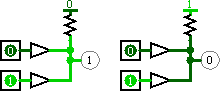
- Label
- The text within the label associated with the gate.
- Label Font
- The font with which to render the label.
- Negate x
- If
yes
, the input is negated before it is fed into the gate. The inputs are counted top-down if the facing is east or west, and they are counted left-to-right if the facing is north or south.
Poke Tool Behavior
None.
Text Tool Behavior
Allows the label associated with the gate to be edited.