Next: User's Guide
Step 4: Testing your circuit
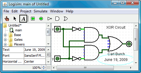
Our final step is to test our circuit to ensure that it really does what we intended. Logisim is already simulating the circuit. Let's look again at where we were.
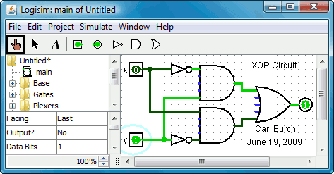
Now to try another combination of inputs. Select the poke tool
(![]() ) and start poking the
inputs by clicking on them. Each time you poke an input, its value will
toggle. For example, we might first poke the bottom input.
) and start poking the
inputs by clicking on them. Each time you poke an input, its value will
toggle. For example, we might first poke the bottom input.
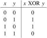
So far, we have tested the first two rows of our truth table, and the outputs (0 and 1) match the desired outputs.
To archive your completed work, you might want to save or print your circuit. The File menu allows this, and of course it also allows you to exit Logisim. But why quit now?
Now that you are finished with tutorial, you can experiment with Logisim by building your own circuits. If you want to build circuits with more sophisticated features, then you should navigate through the rest of the help system to see what else you can do. Logisim is a powerful program, allowing you to build up and test huge circuits; this step-by-step process just scratches the surface.
Next: User's Guide