- Logisim home page
- Guide to Being a Logisim User
- Library Reference
The Simulation tab
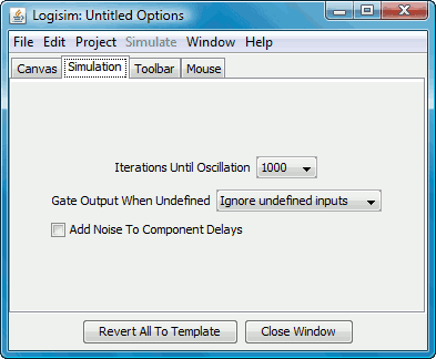
The Simulation tab allows configuration of the algorithm used for simulating circuits. These parameters apply to all circuits being simulated in the same window, even for circuits that exist in other libraries loaded within the project.

The Iterations Until Oscillation drop-down menu specifies how long to simulate a circuit before deciding that it is oscillating. The number represents the number of clicks of the internal hidden clock (a simple gate takes just one click). The default of 1,000 is good enough for almost all purposes, even for large circuits. But you may want to increase the number of iterations if you are working with a circuit where Logisim reports false oscillations. This is unlikely to be a problem in practice, but one such a circumstance is a circuit that incorporates many of the below latch circuits with random noise enabled. You may want to decrease the number of iterations if you are working with a circuit that is prone to oscillating and you are using an unusually slow processor.
The Gate Output When Undefined drop-down menu configures how the built-in logic gates behave when some inputs are unconnected or are floating. By default, Logisim ignores such inputs, allowing a gate to work over fewer inputs than it was designed for. However, in real life, a gate will behave unpredictably in such a situation, and so this drop-down menu allows one to change the gates so that they treat such disconnected inputs as errors.
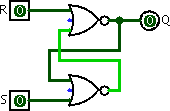
The Add Noise To Component Delays checkbox allows you to enable or disable the random noise that is added to the delays of components. The internal simulation uses a hidden clock for its simulation, and to provide a somewhat realistic simulation, each component (excluding wires and splitters) has a delay between when it receives an input and when it emits an output. If this option is enabled, Logisim will occassionally (about once every 16 component reactions) make a component take one click longer than normal. This randomness is added specifically for handling latch circuit (as below): Without the random noise, the circuit oscillates, since the two gates will work in lockstep; but with random noise added, one gate will eventually outrun the other.

I recommend keeping this option off, as this technique does introduce rare errors with normal circuits.
Next: The Toolbar tab.